ET-SoC-1 · experiment plan · rung 9 of the observability ladder

Pointing a thermal camera at the ET-SoC-1

The P3 cannot resolve a shire, but it can show which package the watts warm: the part of the card's power that no meter sees. The workloads are under exact software control, so lock-in averaging turns a 35 mK camera into a 0.2 mK one. That is enough to tell compute heat, DRAM heat and mesh heat apart.

0.23 mKlock-in noise per pixel after 30 min (NETD 35 mK at 25 Hz)
15.1 Wof a 31.8 W idle card reaches no metered rail — the first thing to image
9–20 mmheat blur across the board at 0.02–0.1 Hz: packages separate, 4 mm shires don't
≈ $190of mounting; ≈ $350 with a Raspberry Pi 5 recording raw frames

Three answers: the back of the PCB later, the relay first, a clamp and a Pi to buy

Point it at the back of the PCB?

Yes, for the long lock-in runs — not for the first shot

The back is one surface with one emissivity (solder mask, 0.90–0.95), no tape needed, and shows the SoC and all four DRAM footprints in a single frame.

But the regulators and the DRAM chips are on the component side, so start with the whole card from the component side at 250 mm. In these open frames the back probably faces the CPU cooler 40–70 mm away; check before buying an arm.

What to run first?

The three-medium relay: equal watts, 30× different data movement

A pipeline stage hands its output through DRAM, the next shire's scratchpad, or its own: 4.34, 4.42 and 5.30 W while moving 48, 593 and 1,484 GB/s.

If heat follows the data, the three images differ. It needs no new code, about 9 minutes of card time, and it shows in the phone app.

What else to buy?

A clamp, a short arm, a cradle, polyimide tape, a Pi

The P3 has no tripod thread, so it needs a cradle; Studio 45's laser cutter makes one in 20 minutes.

Raw 16-bit frames come through an open Linux driver (not macOS), so a Pi 5 on the tailnet records them without touching the shared lab hosts.

Compute, memory and mesh each have their own regulator, 30–80 mm apart on the card

That is why a camera that cannot see a shire can still test the theory. Pick a load to see which parts the repo's measurements predict will warm.

Card layout with the parts predicted to warm under the selected loadPCIe edgeSoCMMMNSRAMDDR · IO bucksDRAMDRAMU15 regulator
V3 dev-card layout from the Apache-2.0 manual (p.3), positions ±5 mm, component side. The production card may place the regulator elsewhere; E-T1's photos settle it.

+27.1 W · fp32 matmul, random data, 1,024 minions

The die rises 5.2 °C in 7 s. The regulator's three minion phases should lose about 5 W more (2.2 → 7.3 W, from the repo's fitted 19.6% loss share). The DRAM should stay flat. The same instructions on zeros add only 2.0 W.

Tested by E-T4 · E-T10

All five loads in one table
LoadPowerWhere the heat should goTested by
Idle31.8 W at 73 °C (aifoundry2)Leakage is most of it: 23 of 36 W at 80 °C. 15.1 W reaches no metered rail — DDR, PCIe, IO and regulator losses. Which bodies sit above board ambient is the first thing the camera ranks.E-T1
Compute+27.1 W · fp32 matmul, random data, 1,024 minionsThe die rises 5.2 °C in 7 s. The regulator's three minion phases should lose about 5 W more (2.2 → 7.3 W, from the repo's fitted 19.6% loss share). The DRAM should stay flat. The same instructions on zeros add only 2.0 W.E-T4 · E-T10
DRAM stream+9.8 W · tensor loads from DRAM · 6.3 W on no metered railThe board's power tree budgets all four DRAM chips at about 3.2 W. So at least 2–3 W of the 6.3 W must be elsewhere: in the die's own DDR controllers (VDD_DDR, up to 4.4 W, under the heatsink at the die's memory edges) and in conversion losses. One 30 s burst on day one shows the split.E-T2b · E-T3
Scratchpad stream+10.5 W · tensor loads from the shire's own scratchpad67% of the extra power lands on the SRAM rail, so the SRAM regulator should light up and the DRAM packages should not. It burns more power than the DRAM stream and puts none of it in the packages.E-T3 · E-T11
Mesh+16.5 W · scratchpad reads 6 hops away · 49% on the mesh railThe single NoC phase should take +2.3 W of conversion loss while each minion phase takes +0.09 W, a 25× contrast. A matmul does the reverse. Which physical phase is the NoC one is not yet known.E-T5 · E-T15

Where to point it: the whole card first, the regulator second, the back of the board for lock-in

TargetDistanceWhat it showsEmissivity prep
1Whole card, component side250 mmEvery package in one frame, ranked against board ambient: the censusnone on mask or mould; tape metal
2U15 minion + NoC regulator100–130 mmThe largest unmetered body: 2.2 → 7.3 W of loss; mesh vs matmul flips which phase heatspolyimide on the module top
3Back of the PCB, over the package150–250 mmThe permanent lock-in view: one emissivity, every footprintnone (solder mask ε 0.90–0.95)
4DDR / IO / Maxion buck band130 mmThe VDD_DDR buck's ~12% loss should answer a DRAM burst and not a matmulpolyimide if metal-topped
5The four DRAM packages120–150 mmThe watts no meter sees — but budgeted ≈ 3.2 W for all fournone (black mould)
6Heatsink base + fin tips150–250 mmA physical owner for the 60–400 s thermal stagespolyimide patch — bare aluminium is a mirror
7Whole rig: card, cooler, neighbour400 mmInlet air, exhaust plume, the airflow changesmatte-black ambient tab

What fits in one frame (40° × 30° lens)

Card layout with the camera's field of view at 100, 150 and 250 mmPCIe edgeSoCMMMNSRAMDDR · IO bucksDRAMDRAMU15 regulator100 mm150 mm250 mm
100 mm: the package and one DRAM (0.28 mm/px). 150 mm: the SoC and all four DRAM (0.42). 250 mm: the whole card (0.70).

Rules for every view

  • Every number is a difference: load minus matched idle, with the camera never moved.
  • 20–30° off normal at most, but 10–15° off dead-on so the camera's own cold reflection misses the hot spot.
  • An ambient tab in every frame: 30 mm of matte-black foam board, which doubles as a null channel.
  • Measure the reflected temperature once with crumpled foil, dull side out, read at ε = 1.
  • Stay out of the frame. A person is the brightest moving thing in the room.
  • Skip: the gold fingers (a mirror), the shunts (~36 mW), and the bare SoC lid, which a heatsink hides.

Lock-in puts every planned signal at least 15× above its noise; the phone app only reads degrees

Predicted signal ranges (bars) against the noise floor at the planned recording length (tick). The ranges come from the fitted thermal chain, measured workload watts and the board's power tree. Where the bracket is wide, the experiment exists to narrow it.

Phone app, radiometric stills
E-T4 U15 regulator body, negative-zero tiles5 K–20 K · noise 100 mK · 50×
E-T2b VDD_DDR buck, 30 s DRAM burst3 K–20 K · noise 100 mK · 30×
E-T2b DRAM package top, 30 s DRAM burst2 K–12 K · noise 100 mK · 20×
E-T4 Heatsink base, 7 s matmul step1.1 K–1.3 K · noise 100 mK · 11×
E-T2 SoC footprint, one relay medium vs another150 mK–400 mK · noise 100 mK · 1.5×
Raw frames + lock-in, 25–60 min
E-T15 NoC regulator phase, mesh load1.7 K–13 K · noise 0.093 mK · 18,280×
E-T11a DRAM package, DRAM vs scratchpad at equal watts900 mK–8.4 K · noise 0.093 mK · 9,677×
E-T9 DRAM package, memory tone510 mK–4.7 K · noise 0.093 mK · 5,484×
E-T9 Heatsink base, compute tone60 mK–80 mK · noise 0.093 mK · 645×
E-T9 Back of PCB over the SoC, compute tone13 mK–65 mK · noise 0.093 mK · 140×
E-T12 Back of PCB, NW vs SE shire masks5 mK–250 mK · noise 0.066 mK · 76×
E-T16 Back of PCB, meter-starving rings1.6 mK–8 mK · noise 0.102 mK · 16×

In the usable band, heat blurs 6–20 mm across the board: DRAM pairs separate, shires don't

Diffusion length versus modulation frequency: across the board heat spreads 6 to 20 mm in the usable 0.02 to 0.25 Hz band, more than the 4 mm shire pitch and far less than the 82 mm between DRAM pairs.usable band0.1 mm1 mm10 mm100 mm0.020.050.10.20.512modulation frequency, HzDRAM pairs, 82 mmmasks, 17 mma shire, 4 mmPCB, in-planealuminiumFR4, through-board
Diffusion length √(α/πf). Copper planes carry heat sideways; FR4 alone barely passes it through.

Noise falls as 1/√time: 30 minutes of frames buys 0.23 mK per pixel

1 min1.28 mK
5 min0.57 mK
10 min0.40 mK
30 min0.23 mK
60 min0.17 mK
\[ \sigma = \mathrm{NETD}\,\sqrt{2/M}, \qquad M = 25\,\mathrm{Hz} \times t \]

Per quadrature, per pixel. The shutter fires every ~90 s and can't be disabled, so every fit carries an offset and a slope per shutter segment. Plan with 4× this until E-T8 measures the real curve: half a pixel of mount wobble on a steep image gradient costs 70–170 mK per frame.

How much of a heat wave crosses the 2 mm board
Frequency0.02 Hz0.050.10.250.9
Amplitude reaching the back, |sech((1+i)L/μ)|0.910.660.390.140.01
Phase lag30°63°96°151°—

One-dimensional, back face treated as adiabatic for the AC wave; real transmission sits between this and e−L/μ. E-T9 measures it.

Twenty experiments: eight in one afternoon with the phone app, the rest on raw frames

Tests the core theory: computation and memory transfers put heat in different places.

About 34 attended hours in six phases, plus 13.5 unattended

Before the cameradie-sensor lock-in, pre-registration, questions to Nate2.5 h
Camera on your deskcharacterise noise, shutter, focus; 90 min soak3.5 h + 1.5 h unattended
Site visit, phone appcensus, relay, DRAM gate, data-dependence, regulator phases4.7 h
Mount and re-baselineclamp, witness marks, idle W and °C in the new configuration2.5 h
Raw-frame lock-in campaignstep response, tones, ladder, commutation, masks, mesh15.5 h
Laterrings and hot line, PRBS, leakage, heatsinks, overnight5.75 h + 12 h unattended

Before the camera arrives

card only
FREE

Lock-in on the die sensor you already have

The whole-degree sensor at 10 Hz still averages to about 3 mK in 30 minutes. Random data on 1,024 minions, 2 s on and 22 s off (2.5 W average, inside the 3 W budget), swings the die 692 mK. That gives an absolute anchor for every later camera number.

high1 h30 min of 2 s launches
FREE

Pre-register every burst

Run predict_heat.py for each planned burst and timestamp the output before the session. The repo already does this for the flip model, and it catches power-match errors before any card time is spent.

freeno card time

Day one: phone app, radiometric stills

degree-scale only; ε = 0.95 for solder mask and DRAM mould
E-T1

Rank what is warm with nothing running

Which bodies sit above board ambient at idle? That ranking is the first proportional split of the 15.1 W that no rail meters.

high60 minno card timewhole card, 250 mm
Protocol and prediction
Also settle
Which rig holds which card; which face of the card you can reach, and how far away; whether the heatsink covers the DRAM; whether a fan is fitted; which board revision. Calibrate emissivity against a contact thermocouple. Record idle W and idle °C with the camera installed.
Refuted if
Nothing but the SoC is above ambient. Then the remainder is inside the package and the regulators, and it stays a regression.
E-T2b

Find where the DRAM watts land

Of the 6.3 W that a DRAM stream puts on no metered rail, how much warms the four chips, how much the die's memory edges, how much the regulators?

high20 min~1 min cardgates E-T3, E-T6
Protocol and prediction
Workload
timeout 10 enercat_host --pattern tload --operands random --harts 1 --slice-bytes 256K --seconds 8 --budget 9, repeated for 30 s; image at 250 mm, then 150 mm.
Why it matters
The board's power tree budgets the four chips at about 3.2 W together (VDD1, VDD2 and VDDQ); VDD_DDR, up to 4.4 W, powers the die's own DDR controllers. A small signal on the packages moves part of the 72.9 pJ-per-DRAM-byte term into the die and the regulators — a result, not a failure.
E-T2

Equal watts, different place: the three-medium relay

A pipeline hands data to the next stage through DRAM, the next shire's scratchpad, or its own: 4.34, 4.42 and 5.30 W while moving 48, 593 and 1,484 GB/s. Does the heat follow the data?

high45 min~9 min cardstart here
Protocol and prediction
Workload
tools/ettelem/run_onchip_power.sh /tmp/ir-relay-N 30 — one out-dir per repeat (it truncates its telemetry), change its timeout 40 to timeout 10, and stop any other sampler first: the script starts its own.
Prediction
dram warms the DRAM side and barely the die. scp warms the die and the SRAM regulator. hop warms the die and the NoC phase. The die-side differences are only 0.15–0.4 °C, marginal in the app; the package side is the discriminator.
Refuted if
All three images have the same shape: board spreading erased placement at 30 s. That sets the resolution limit.
E-T3

DRAM stream vs scratchpad stream, and memory's own data-dependence

Random operands cost 9.84 W, zeros 7.09 W, for identical bytes: 1.46 W of the gap is off-rail. The scratchpad stream costs 10.51 W, two-thirds on the SRAM rail. Which packages move?

medium35 min~3 min card
Protocol and prediction
Workload
The E-T2b line with --operands random then zeros. The scratchpad control needs a prefill first — enercat_host --pattern tstore --operands <o> --slice-bytes 32K --scp — because enercat skips the operand fill for --scp.
Cross-check
The card's DDR-rail droop (die_mv.ddr) should read about 5.6 and 3.9 mV — the one on-card sensor that answers to DRAM traffic alone.
E-T4

Same instructions, different data

Random fp32 data adds 27.1 W, zeros 2.0 W, at the same instruction rate. Negative zeros are not gated and cost like ones (+10.6 W). Does the regulator follow the data?

high30 min~2 min card
Protocol and prediction
Workload
timeout 10 sparsity_host --test fma --type fp32 --pattern none --values randn --shires 0xffffffff --per-shire 32 --seconds 7 --budget 9 --seed 1, then --values zeros, then --values file: tiles from make_tiles.py negzero. Start from 80 °C by the strict protocol.
Prediction
Die +5.2 °C in 7 s, heatsink base only +1.3 °C. The three minion phases lose 2.2 → 7.3 W. Negative zeros land where ones do, not where random data does.
E-T5

Find the NoC phase of the regulator

A mesh load should heat one regulator phase by +2.3 W and each minion phase by +0.09 W; a matmul does the reverse. The crossover names the phase and tests the repo's fitted 19.6% and 28.6% loss coefficients.

medium30 minregulator, 100–130 mm
Protocol and prediction
Workload
The catalogue's wire/hop6/random line verbatim: --pattern tload_pat --operands random --hop-distance 6 --slice-bytes 32K --stride 1K --access-bytes 1K --region 32K, after a tstore --scp prefill. Minion arm: the E-T4 line.
Measure
Each body minus its local copper pour: all four phases share one plane, so expect a 2–8 °C workload contrast, not 5–20 °C between bodies.
E-T6

Which DRAM pair does address bit 8 select?

PA[8:6] picks the memory shire; four memory shires sit on each side of the die. Force PA[8] and one DRAM pair should warm, 82 mm from the other — or none will, which means the interleave is finer.

medium-low75 minneeds a 15-line table writer
Protocol and prediction
Workload
memprobe_host with the dram_row parameters (--level 4 --stride 262144 --lines 1024, from gen_ops.py table) and PA[8] forced; snapshot the eight memory-shire counters with msmap in the same session.
Confounds
PA[8] also sits inside the L3-home field, so run the same table at a cache-resident level as a control. The camera says which packages warmed; the counters say which memory shires were hit.
E-T7

Watch the whole rig's airflow, every session

Mid-session the lab's airflow once dropped the die 12 °C at constant power. One wide frame of card, cooler and neighbour at 400 mm, at the start and end of every session, catches that.

high10 minno card time

Week one: raw frames on the Pi, lock-in

HIGH gain, camera warm 15 min, shutter events masked
E-T8

Characterise the camera before trusting a millikelvin

Does this unit's noise fall as 1/√frames down to 0.4 mK in 10 minutes, or plateau? How often does the shutter fire, and does a manual fire reset its timer? Where are the fan lines in the room's spectrum?

gate2.5 h + 90 min soakno card time
Protocol and prediction
Deliverables
A measured noise-vs-time curve, a spectrum of the rig at the final mount (choose the tones from its gaps), a shutter playbook, ROI masks and a saved home frame. Quote the null-patch amplitude beside every later result.
E-T13

Step response: give each thermal stage a physical owner

The fitted chain has stages at 1.5, 4, 60, 150, 400 and 2,500 s. Which object is each — lid, heatsink base, fins, air? And aifoundry3's chain has never been fitted: this sets its power budget.

high2 h~30 min cardbudget gate for a3
Protocol and prediction
Protocol
aifoundry3: 10 min idle, repeated 0.5 s random-data launches with --stop-file and an 85 °C watchdog until the cap or 10 min, 15 min cool; three steps. Needs your explicit waiver of the 10 s rule.
Stronger version
Amplitude and phase at lid edge, heatsink base, fin tip and board, at three frequencies, is a direct Cauer-ladder measurement — which a single-node Foster fit can never be.
Control
A resistor heater on a spare heatsink of the same type (E-T13b, offline) separates the sink's own stages from the package path.
E-T9

Compute tone, memory tone, compute tone

Where do compute watts land and where do memory watts land, in °C per watt, pixel by pixel?

medium-high5 h over 2 views~20 min card per record
Protocol and prediction
Workloads
Compute at 1/21 Hz, 5 s on: sparsity_host --test fma --type fp32 --pattern none --values randn --shires 0xffffffff --per-shire 8 --seconds 5 --budget 6 --seed 1 (256 minions, 6.8 W, 1.6 W average). Memory at 1/28 Hz, 10 s on: the E-T2b enercat line with --seconds 10 --budget 11. 5 min unrecorded, then 30 min recorded each, in an unmoved mount.
Why serial
Two workloads cannot share the card at half-second granularity, so frequency-multiplexing them in one record puts about half the memory excitation into the compute channel.
The number to keep
The fraction of die heat that takes the board path. Every back-of-PCB prediction on this page is a 3–15% bracket until this measures it.
E-T10

Make every image a wattmeter

Eight operand patterns span 1.9 → 27.1 W of switching at identical instructions, clock and voltage. Fit each ROI's rise against watts plus the leakage feedback — the result is a per-pixel °C/W map.

high90 min~10 min card
Protocol and prediction
Workload
run_horace_strict.sh <out> 80 84 4 3 1 7 "zeros ones pi signs mant uniform randn sparse50" "" on aifoundry2, and the same ladder on aifoundry3.
Test against
predict_heat.py's predicted superlinearity, not a straight line: the existing ladder already has a −0.44 °C intercept from leakage feedback. The DRAM should stay flat — and that flatness is the result.
E-T11

Swap two sources at equal watts — with a null that must stay dark

Alternate A and B at 0.025 Hz with total power held constant: pure relocation shows at f, the common mode at 2f. Pairs: DRAM vs scratchpad stream; int8 matmul (9.98 W) vs DRAM stream (9.84 W); and the null — int8 on 1,024 minions vs fp32 on ~384 (same watts, same place).

medium4 h~50 min cardflagship
Protocol and prediction
Guard
If the null pair shows anything at f above the null-patch floor, the pipeline is making artefacts and the other two pairs are void.
Power match
Titrate each pair to within 0.5 W, then use the residual board-power amplitude at f as a regressor: 0.5 W unmatched is 62 mK on the die, about 19% of the relocation signal.
E-T12

Anti-phase shire masks: the honest marginal case

Run 8 shires in the north-west corner against 8 in the south-east, 6.8 W each, centroids 14–18 mm apart, and look for the heat moving on the back of the PCB.

low as a map, high as a bound90 min~25 min card
Protocol and prediction
Masks
--shires 0x0101031b vs 0xc4c080c0. Capture the SP's per-shire IR-drop voltage map during both halves: the voltage map says where the current went, the camera says where the heat went.
If it's a null
Publish the upper bound in mK and W/mm². The repo has no such number, and it would constrain every future spatial claim.
E-T14

Log the heatsink's state at every launch

Ones on 1,024 minions reached 90 °C in 107 s after a hot predecessor and in 162–167 s after a zeros run, from the same 80 °C reading. The missing state variable is the heatsink; one ROI in starts.jsonl measures it.

freeno extra card time
E-T15

Mesh traffic: does the path heat, or only the endpoints?

A hop costs 131 fJ per bit, and a 6-hop read puts 49% of its power on the mesh rail. Does ~6 W moving from the SRAM arrays into the mesh show as a band across the die?

medium1.5 h~30 min card, a3
Protocol and prediction
Signal
Board back: 10–60 mK, as marginal as E-T12. The regulator split is large: 1.7–13 °C at f on the NoC phase. E-T15 + E-T11a + E-T10 close the {compute, DRAM, mesh} triangle.

Later

after the rig is proven
E-T16

Read watts from the image when the meter freezes

Rings between shires s and s+16 stall the service processor and make bursts read 45% low. The camera doesn't go through the SP. Part B: the contended hot line (+1.41 W) should show no hot spot.

medium70 minneeds a remote power cycle
Protocol and prediction
Risk
A minion receiving readies from two TensorSend partners hangs permanently and needs a power cycle — from far away. Ask Nate whether a remote power cycle exists first.
E-T17

A per-pixel impulse response from a pseudo-random drive

An m-sequence of 4 s chips gives every pixel's impulse response, and the low-frequency rise of Z(f) measures how close the die is to thermal runaway without ever running away.

medium90 min~35 min card
E-T18

Leakage global, switching local

During a climb driven by one masked corner, the whole die should brighten while only the corner switches, so the corner's contrast should shrink as the die heats.

low1 h
E-T19

Image both heatsinks, and the 2,500 s stage overnight

aifoundry3 sheds heat visibly faster. Same strict protocol, camera on each heatsink in turn; the slowest stage as an overnight idle equilibrium.

medium2 h + overnight
Not for a shared card without the lab admin: removing a heatsink (and a bare lid is isothermal, so you'd see almost nothing), moving aifoundry2 onto a riser (88 W peaks against a 66 W slot, and the aux 12 V may bypass the current sense), changing aifoundry2's airflow, or reflashing aifoundry3's TDP. If there is a spare or dead card, that is where these belong. On removing the heatsink, the follow-up report Feasibility of running the ET-SoC-1 without its heatsink estimates that a bare card at 600 MHz almost never settles at idle, and that bare aifoundry2 in still air passes 90 °C 1–3 minutes after a cold power-on at idle (card 1 in 41–99 s).

Mount it on the rig's own shelf, with a short arm, and never move it again

Side view of the mount: a super clamp on the shelf tube, an arm of at most 140 mm, a ball head and a cradle hold the camera 250 mm from the card's face; the USB cable is tied down near the camera and runs to a Raspberry Pi. wire shelf, the same one the rig sits on shelf tube super clamp arm ≤ 140 mm P3 in a cradle cable tied down USB → Pi 5 250 mm: whole card, 0.7 mm/px ET card, edge-on heatsink side toward camera motherboard
Schematic side view. A fixed cheap camera beats a better camera that moves.
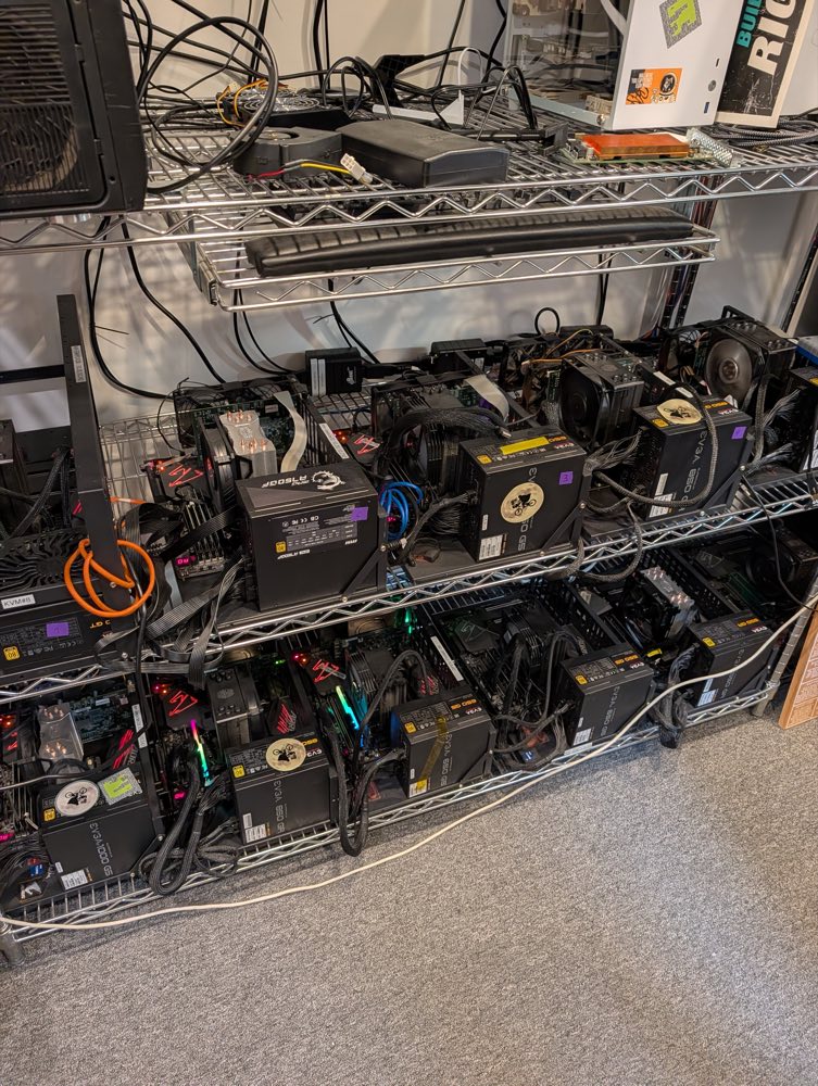
The Studio 45 rack: chrome wire shelving with open-frame test benches on two shelves, EVGA power supplies and tower CPU coolers
Your rack. Posts stand only at the two ends, with 4–5 rigs per shelf. No ET card is identifiable here.
  1. Resolve the geometry first. Get photos of the ET card in its rig: one along the board face, one showing the gap to the nearest obstruction with a ruler in shot. Framable width ≈ 0.73 × the clear distance.
  2. Re-baseline. Record idle watts and idle die temperature with everything installed. The 1.47 °C/W chain, the 3 W budget and the 80 °C start all belong to the old configuration.
  3. Anchor to the same shelf as the rig. In order: a nearby post, the shelf's perimeter tube, a magnetic base on a steel PSU case, a laser-cut bridge across two shelf wires. Not the shelf with the pull-out keyboard tray.
  4. Arm ≤ 140 mm, cradle on the body. The USB-C plug is the camera's only attachment point, so the cradle's cable clamp must take every tug.
  5. Focus once and lock it. Focus on a soldering-iron tip at the working distance. Warm the camera 15–20 min, use HIGH gain only, and fire a manual shutter before each run.
  6. Tape metal targets with permission. Card de-energised, polyimide only, never near the die–heatsink interface or a fan. Put fiducial dots on the mount, not the card.
  7. Strain-relieve within 100 mm and keep 25 mm of metal clearance from the PCB. Wear a wrist strap if you reach in.
  8. Mark and label. Witness marks on the clamp and arm knuckles; a “measurement in progress, please don't move — ping Yaroslav” tag; a saved home frame at the start and end of each session; a named person at Studio 45 who re-aims if it gets bumped.

Shopping list: ≈ $190 of must-haves, ≈ $350 with the Pi

ItemWhyExample~Price
Super clamp, 10–55 mm jawsThe rigid anchor; 10 mm closes on a ~12.7 mm shelf tubeSmallRig 2058$25–40must
Articulating arm ≤ 140 mmShort arms resonate less on a shelf full of fansSmallRig 2065 (5.5 in)$30–45must
Mini ball head, 1/4-20Fine aim within 20–30° of normalany$15–25must
Cradle with a cable clampThe P3 has no tripod thread; the USB-C plug must never carry loadlaser-cut at Studio 45, or the Printables “Thermal Master P3 Holder”$0–10must
Magnetic base, 1/4-20Fallback anchor on a steel PSU caseany$15–25must
USB 2.0 extension, 2 m A-to-AAfter the included 0.5 m C extension and A adapter; longer passive C-to-C is out of specAnker, Cable Matters$10–15must
Polyimide tape, 1 mil totalε ≈ 0.9 on metal, insulating, 260 °C, removablegeneric 1 mil; 3M 5413 is 2.7 mil (≈ 6 K offset)$8–12must
Contact thermometer (K-type or DS18B20)Solves ε and reflected temperature instead of guessing themany$15–30must
Matte-black foam board, zip ties, gaffer tape, paint penAmbient tab, background, strain relief, witness markscraft store~$25must
First-surface mirror, 50 mm, Al or Au> 95% at 8–14 µm — the fallback if the back of the PCB faces a CPU cooler. Household glass mirrors are opaque in LWIRThorlabs / Edmund$25–40if needed
Raspberry Pi 5 + 1 TB USB SSDRaw 16-bit frames need Linux; your box on the tailnet, 8.9 GB/h off the lab diskPi 5 4 GB~$160strongly
Hot-wire anemometerPuts a number on the airflow changesany$25–35nice

Budget version (~$50): a gooseneck clamp phone holder, polyimide, foam board, the USB path and gaffer tape. That covers day one and none of week one. Don't order SmallRig 2064 (an EVF bracket, not a clamp), the Manfrotto 244MINI (240 mm, too long), 3M Super 33+ vinyl (105 °C, leaves residue) or a PCIe riser.

Record raw frames on a Pi, join them to the runner's logs by the clock, and read out °C per watt

P3, 25 Hz256 × 192 native; 16-bit temperature rows, T = raw/64 − 273.15 (1/64 K steps)
→
Pi 5 on the tailnetjvdillon/p3-ir-camera (Apache-2.0, Linux); 8.9 GB/h; frames stamped in epoch ms
→
Join on epoch msrunner starts.jsonl + ettelem at 10 Hz on aifoundry2/3
→
Demodulate per pixelregister → 2 Hz → fit tones + per-shutter offset and slope → a complex °C/W map
The analysis code (numpy): lock-in demodulation and PRBS impulse response

Tested here on synthetic data: 1,800 s at 2 Hz, shutter segments every 90 s with random offsets and slopes, quadratic drift, NETD noise. A true 3 mK channel came back as 3.07 ± 0.23 mK, σ on theory. Dropping the per-segment slope inflates the noise and lets drift leak into null pixels. Download lockin.py.

"""Lock-in / PRBS demodulation of a Thermal Master P3 raw stack, joined to ettelem telemetry.

temp : float32 (M,192,256) degC = thermal_u16/64.0 - 273.15   (rows 194..385 only),
       already registered and boxcar-decimated to ~2 Hz
t    : float64 (M,) host monotonic seconds -- REAL timestamps, never frame indices
seg  : int32  (M,) increments at every detected FFC/shutter event
good : bool   (M,) False for shutter epochs (+2 s) and cnt3 gaps -- drop, never interpolate
extra: (M,k)  covariates: the REALIZED launch indicator or board_w, the residual board_w
              amplitude term, camera body temperature, the ambient tab ROI
"""
import numpy as np


def design(t, freqs, harmonics=3, seg=None, seg_order=1, drift_order=2, extra=None, res_hz=None):
    """[per-FFC-segment offset AND slope | covariates | cos/sin per (freq, harmonic)].

    With seg given, NO global drift polynomial: the per-segment piecewise-linear basis
    already spans every global affine function, so adding drift^1 makes X exactly
    rank-deficient (cond ~1e16) and np.linalg.inv returns garbage without raising.
    seg_order >= 1 is mandatory: without the slope, sigma inflates 5x and a null pixel
    reads 2.7 mK against a true 3 mK channel.
    """
    cols, names = [], []
    t = np.asarray(t, float)
    if seg is None:
        u = 2 * (t - t.mean()) / max(np.ptp(t), 1e-9)
        for p in range(drift_order + 1):
            cols.append(u ** p); names.append(f"drift^{p}")
    else:
        for k in np.unique(seg):
            m = seg == k
            tc = np.zeros_like(t); tc[m] = t[m] - t[m].mean()
            sc = max(np.ptp(t[m]), 1e-9)
            for q in range(seg_order + 1):
                c = np.zeros_like(t); c[m] = (tc[m] / sc) ** q
                cols.append(c); names.append(f"seg{k}^{q}")
    if extra is not None:
        for j, col in enumerate(np.atleast_2d(np.asarray(extra, float).T)):
            cols.append(col - col.mean()); names.append(f"extra{j}")
    tones, res = {}, res_hz if res_hz else 1.0 / max(np.ptp(t), 1e-9)
    for f in freqs:
        for h in range(1, harmonics + 1):
            fh = f * h
            for g in tones:                       # key by (f,h), never by formatted name
                if abs(g - fh) < 2 * res:
                    raise ValueError(f"tone collision: {fh:g} Hz vs {g:g} Hz (res {res:.2g} Hz)")
            tones[fh] = len(cols)
            w = 2 * np.pi * fh
            cols += [np.cos(w * t), np.sin(w * t)]
            names += [f"cos{fh:.6g}", f"sin{fh:.6g}"]
    return np.column_stack(cols), names, tones


def demodulate(temp, t, freqs, good=None, seg=None, ref_mask=None, harmonics=3,
               seg_order=1, drift_order=2, extra=None, block=512, cond_max=1e8):
    """Per-pixel LSQ lock-in at several frequencies, chunked over pixels.
    Returns {freq: dict(amp[K], phase[deg lag], sigma, snr)} plus '_cond'."""
    if good is None: good = np.ones(len(t), bool)
    tg = t[good]; sg = None if seg is None else seg[good]
    eg = None if extra is None else np.asarray(extra)[good]
    X, names, tones = design(tg, freqs, harmonics, sg, seg_order, drift_order, eg)
    s = np.linalg.svd(X, compute_uv=False)
    cond = s[0] / s[-1]
    assert cond < cond_max, f"design matrix ill-conditioned: cond={cond:.3g}"
    XtXi = np.linalg.inv(X.T @ X)                 # safe only after the cond assertion
    P = np.linalg.pinv(X)
    H, W = temp.shape[1], temp.shape[2]
    npx, dof = H * W, len(tg) - X.shape[1]
    beta = np.empty((X.shape[1], npx)); sigma = np.empty(npx)
    ref = None
    if ref_mask is not None:                      # common mode: unpowered taped patch
        ref = temp[good][:, ref_mask].reshape(len(tg), -1).mean(axis=1)
    flat = temp[good].reshape(len(tg), npx)
    for i in range(0, npx, block):                # 512 px x 3600 frames = 15 MB, Pi-safe
        Y = flat[:, i:i + block].astype(np.float64)
        if ref is not None: Y -= ref[:, None]
        b = P @ Y; r = Y - X @ b
        beta[:, i:i + block] = b
        sigma[i:i + block] = np.sqrt((r * r).sum(0) / dof)
    out = {"_cond": cond}
    for fh, i in tones.items():
        c, sn = beta[i], beta[i + 1]
        sig = sigma * np.sqrt(0.5 * (XtXi[i, i] + XtXi[i + 1, i + 1]))
        amp = np.hypot(c, sn)
        out[fh] = dict(amp=amp.reshape(H, W),
                       phase=np.degrees(np.arctan2(-sn, c)).reshape(H, W),
                       sigma=sig.reshape(H, W),
                       snr=(amp / np.maximum(sig, 1e-12)).reshape(H, W))
    return out


def mseq(n, taps):
    """Maximal-length LFSR, +-1, L = 2**n-1. n=7 taps=[6]; n=9 [5]; n=10 [7].
    Periodic autocorrelation is exactly L at lag 0 and -1 elsewhere; check s.sum()==1."""
    mask = L = (1 << n) - 1; reg, out = 1, []
    for _ in range(L):
        out.append(1.0 if (reg & 1) else -1.0)
        fb = reg & 1
        for tp in taps: fb ^= (reg >> (n - tp)) & 1
        reg = ((reg >> 1) | (fb << (n - 1))) & mask
    return np.array(out)


def prbs_impulse(temp, t, seq, chip, t0, good=None, detrend=2):
    """Per-pixel thermal impulse response by periodic cross-correlation.
    Per-lag noise ~ NETD/sqrt(M) -- sqrt(2) better than single-frequency lock-in, and
    L lags instead of one amplitude. cumsum(h) is the step response; fit Foster taus to
    that. DC gain is lost with the mean -- take it from E-T13."""
    if good is None: good = np.ones(len(t), bool)
    L = len(seq); period = L * chip
    tg = t[good]
    b = np.floor(((tg - t0) % period) / chip).astype(int)
    Y = temp[good].reshape(len(tg), -1).astype(np.float64)
    V = np.vander(tg - tg.mean(), detrend + 1)
    Y = Y - V @ np.linalg.lstsq(V, Y, rcond=None)[0]
    acc = np.zeros((L, Y.shape[1])); np.add.at(acc, b, Y)
    cnt = np.bincount(b, minlength=L).astype(float)
    y = acc / np.maximum(cnt, 1)[:, None]
    y = y - y.mean(0, keepdims=True)
    S = np.fft.rfft(seq)
    h = np.fft.irfft(np.fft.rfft(y, axis=0) * np.conj(S)[:, None], n=L, axis=0) / (L + 1)
    return h.reshape(L, *temp.shape[1:])
Six traps, each of which has already cost this project time

The governor makes coherent artefactsaifoundry2 steps its clock down above 65 °C or 65 W and back up below. If the open frame cools it near that line, the clock steps lock to your modulation. Prefer aifoundry3 (pinned at 600 MHz), preheat a2 to ≥ 76 °C, and drop any burst whose mhz.minion left 600.
The shutter can't be turned offThe P3 recalibrates about every 90 s even when not streaming. Detect each event from the stream, mask 2 s, keep an offset and slope per segment, dither manual triggers over 60–85 s, and choose tones off the n/90 s comb: 1/21 Hz and 1/28 Hz.
A 3 W sustained budget on aifoundry22.7 W of switching cools; 3.4 W holds 81–82 °C; 4.2 W creeps to 87 °C. aifoundry3's budget is unknown until E-T13. Only sparsity_host polls --stop-file; for the others the guard is "don't launch the next burst", so keep ~3 °C of margin.
One opener on the management nodeThe runners start their own ettelem; a second sampler makes them fail. Quit et-powertop and et-power-log.sh first and restart them after. Some mesh workloads starve the meter (sampler latency 22 → 150 ms, bursts read 45% low); watch took_ms.
The room is part of the experimentAirflow once moved the die 12 °C at constant power. Install any hood or background before the baseline and never touch it; log the camera body's own temperature, which the card's exhaust modulates at your frequency.
The cards are sharedAsk which machine; check uptime, ps and the driver's open count; nothing holds the card over 10 s without your explicit waiver (E-T13, E-T17). The lock-in runs are 30–90 min windows: book them with Nate and note them on the rig.

Questions for Nate before the first visit

  1. Which rig is aifoundry2 and which is aifoundry3? The rigs carry labels (OPEN-FRAME-nn, KVM numbers); map them to hostnames.
  2. Two close-ups of each ET card in its rig, one along the board face and one with a ruler across the gap to the nearest obstruction. Which face is reachable, and at what distance?
  3. How far is the card from the nearest shelf post, and what is the shelf tube's diameter?
  4. Does the heatsink cover the DRAM? Is a fan fitted? The board has a fan header; a fan changes every convection assumption.
  5. Which board revision? The blue V3 dev card or the green production card? The regulator moves between them.
  6. Is the green board with the copper block on the top shelf a spare ET card? The production card is green with a bare copper spreader. If it is, it's the best bench target in the room and the only ethical home for heatsink-off work.
  7. Is the 6-pin aux 12 V (P7) plugged in? Per the power tree it joins after the current sense, so its current may not show in board power.
  8. Is there a remote power cycle? Required before any nocbench work.
  9. May a clamp stay in place indefinitely, with polyimide patches on which card? And who re-aims the camera if it gets bumped?

How this plan was made

Five research agents covered the camera, the board and die floorplan, the repo's theories and tools, lock-in technique, and mounting. Three designers wrote independent plans (hypothesis-first, instrument-first, pragmatic), an editor merged them, and three adversarial reviewers checked the physics, every repo number and tool flag, and the camera facts. 58 of their corrections are applied: the shutter can't be disabled, frequency-multiplexing two workloads doesn't work here, and several command lines would have measured the wrong thing. The key repo numbers, the driver and the analysis code were re-checked by hand. Nothing was run on a card. The full plan (markdown, 130 KB) has every derivation, command and caveat.

Sources